Silicon Valley Automation
Modern technologies with old-fashioned professional pride
Modern technologies with old-fashioned professional pride
AFAB™ – A BETTER WAY
TO LEVEL YOUR HARDWARE
TO LEVEL YOUR HARDWARE
| | | | | | |
Fig. 10
Fig. 11
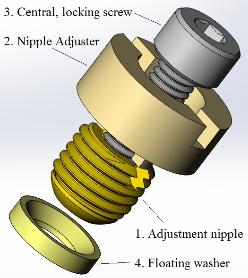
Advanced AFAB Kits
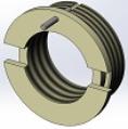
The main addition to the advanced AFAB kit (Fig. 10) is a floating washer (4) with a cone
shaped indentation, which receives a profoundly rounded bottom end of adjustment nipple (1).
Additional two components, nipple adjuster (2) and central, locking screw (3) are the same as
for the standard version of AFAB kits. The screw, however is usually longer and its length is a
function of one of a few possible applications (Fig. 11).
For most applications, the floating washer should be installed in a counterbore with a diameter
slightly larger than the diameter of the washer. Such installation allows the washer to move in
X and Y direction (to “float”) and compensate for small machining errors, and/or larger tilts.
In spite of the above statement, the washers are machined with very tight tolerances (+0/-.
002”). Such tolerance becomes very useful if the X-Y positioning of a device is critical. In such
situation, it is advisable to press fit the washer for the most critical leveling foot, while
installing other two in oval, precisely machined perpendicular slots.
Although the performance of such adjustment mechanism is very good and can satisfy a big
majority of application, it is still possible to make an improvement by adding other degrees of
freedom, which entirely release adjustment mechanisms from their intrinsic stresses.
Fig. 11 shows six configurations and applications of the adjustment mechanisms.
All parts of these configurations are designated with
numbers having the following meanings:
1. Adjustment nipple,
2. Nipple adjuster,
3. Central, locking screw,
4. Floating washer,
5. Floating nut,
6. Spherical Nut,
7. Washer,
8. Retaining ring,
9. Insert,
10. Top plate,
11. Base
12. Machined cone shape
13. Counterbore for the floating washer (shown
only on Assy. 3, but applies to 3 – 6)
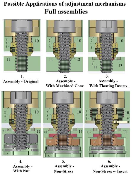
Assembly 1 – Original, is an implementation of
the simplest version of the adjustment mechanism
shown in Fig. 2. The assembly is inexpensive, easy
to use and provides long-term very stable alignment.
Assembly 2 – with the machined cone is an
implementation of the adjustment mechanism with
the nipple with a spherical head like the version from
Fig. 10 but without the floating washer. The washer
in this version is replaced with a cone-shaped
indentation machined directly in the base of the
machine. Similarly, to the previous one, the
assembly is inexpensive, easy to use and provides
long-term very stable alignment.
Assembly 3 – is the full implementation of the
version from Fig. 10. Slightly more expensive than
the previous one provides the same very good
performance and can be used with heavier loads.
Assembly 4 – Provides the additional degree of
freedom by implementing a floating nut. The central
screw can perform small X-Y movements, which
contribute to lowering the stresses intrinsic to the
assembly. The cost of the components is marginally
higher than for assembly 3 (additional nut, and optional washer, and retaining ring), but one needs to consider the increased cost of machining of the
base. The superb performance of this adjustment mechanism allows one to use it for very demanding applications.
base. The superb performance of this adjustment mechanism allows one to use it for very demanding applications.
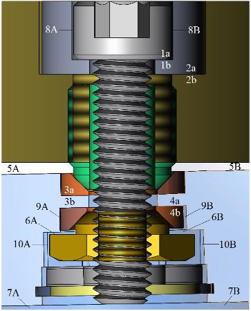
Assembly 5 and 6 – is an ultimate, stress-free method of
alignment. The nut from assembly 4 was replaced with a
spherical nut and a mating, second floating washer. Fig. 10
shows how such mechanism works in an extreme case. On the
drawing, the base is tilted by 2°, while the top plate compensates
for this tilt and is adjusted to a horizontal position (please
compare gaps 5A-5B, 6A-6B, and 7A-7B). To achieve such
result all swivel-able components had to be tilted and shifted
(please see uneven gaps 8A-8B, 9A-9B and 10A-10B). Despite
these tilts, all components participating in locking the position of
the mechanism are perfectly aligned. In the top plate the surface
under the screw head (1a) and the bottom of the nipple adjuster
counterbore (1b), as well as the surface under the nipple adjuster
(2a) and the bottom of the counterbore for the adjuster (2b) are
coincident. Similarly, the lower surfaces of both floating washers
in the base are coincident with bottoms of corresponding
counterbores (surfaces 3a, 3b, and 4a, 4b). The axis of the screw
and the nut are also coincident. All these observations lead to
the conclusion that in this arrangement there are no stresses
intrinsic to the adjustment mechanism.
This assembly requires two additional components: the second
floating washer, and the spherical nut. That’s why the cost of
the assembly is obviously higher. The cost of machining of the
base plate is also higher and should be considered when budgeting
a new project, but the superb performance of this adjustment
mechanism totally justifies its usage for systems requiring very
high quality, stable alignment
The sixth drawing in the application table shows an additional component – an insert (9) & (Fig. 13). It is a
very precise, hollow stainless-steel nipple with internal and external threads, locking pin, and a collar for a
precise bottom installation. The inserts were designed to address concerns of some designers that threads in
aluminum blocks are not strong enough, reliable and enduring to support sometimes a very expensive equipment.
Fig. 11
Fig.12
Fig. 13